Compression Optimization Improves Performance Of Gathering Systems
By Gary Bourn and Mike Sutton
DENVER–Rapid compression capacity expansions in gas gathering systems in unconventional resource plays, followed by the commodity price downturn, has driven the need to increase efficiency and reduce operating costs. This challenge is compounded by the effects that highly dynamic upstream field conditions have on gathering compressors, especially when fed by multiple wells in large-scale field developments.
Given variable well conditions and the design parameters of the types of compressors used in gathering–relatively small-capacity, multistage units with minimal automation to allow for portability from one location to another–average throughput utilization of gathering compressor fleets can be poor unless the units are adjusted continuously.
Anadarko Petroleum Corp. initiated a compressor optimization program last year to safely increase utilization and gathering system performance through advanced monitoring and active operator engagement. The program was implemented in the company’s Greater Wattenberg Area in the Denver-Julesburg Basin, achieving an overall 10-15 percent increase in station throughput. The greater capacity has enabled increased base production despite a decrease in drilling and completion activity. The program now is being deployed in all Anadarko gathering assets.
After extensive modeling showed the throughput of the Wattenberg gathering compression fleet could be increased significantly with more routine adjustments, the optimization program was developed to:
- Create an in-depth equipment database and build detailed models of all compressors, including load step schedules;
- Create intuitive and easy-to-interpret tables of load step schedules to distribute to operations personnel;
- Internally develop an optimization tool to automatically look up the optimal settings for maximum throughput at existing conditions within safe operating boundaries;
- Construct human-machine interface screens to display current conditions and compressor utilization, recommended settings, and predicted gains from adjustments;
- Work with operations to implement the recommendations; and
- Document improvements and search for other opportunities to further increase companywide compression utilization and efficiency.
Wattenberg Gathering System
The Wattenberg gathering system includes approximately 180,000 horsepower of compression with a nominal processing capacity of 1.1 billion cubic feet a day, and more than 2,100 miles of pipelines. Unprocessed gas is gathered and delivered to four Anadarko-owned processing plants. The majority of gas originates from Anadarko’s production, but a portion is from third-party producers.
Compressor stations typically consist of multiple compressors, with a few outlier stations with one or two smaller units. Of the 89 gathering compressors in Wattenberg, 42 are of like-kind designs: four-throw, three-stage compressors that Anadarko refers to as “3606 packages.” The engine driver is a Caterpillar G3606-A3™ with a nameplate rating of 1,775 horsepower and site-rated power of 1,680 hp when derated for elevation and maximum ambient temperature.
The compressor is an Ariel JGK™/4-3 with bores of 14.125 inches for the two first-stage cylinders, 10.5 inches for the second stage, and 6.75 inches for the third stage.
The particular design features relating to control of the 3606 packages include:
- Manual variable volume clearance pockets (VVCPs);
- Manual bypass valves;
- Unit programmable logic controllers to control engine speed for startup and shutdown, and overrides for high-discharge, low-suction and high temperature;
- Unit PLC control of inlet suction pressure using individual or bank control valves; and
- Engine-driven cooler fans (two) with pneumatic control of louvers for individual process temperature control.
Prior to developing the optimization tool, the typical compressor operation was to set the suction control set point to a fixed pressure and adjust the VVCP through trial and error to a position such that the unit provided the “nominal” throughput. Nominal throughput is a round number that approximates the throughput at some typical suction and discharge condition. It is a useful number for overall gathering system design to determine how many compressors are needed to match expected production rates. The nominal throughput value also was used as the basis to determine if a unit was being fully utilized.
However, when detailed modeling and analysis of the Wattenberg compression fleet began in 2013-14, it quickly became evident that compression throughput could be significantly greater than the nominal rate. Among the factors that can affect compressor throughput are engine load levels, suction-pressure set points, and actual VVCP positioning. Suction-pressure set points and VVCP positions typically were set to provide a conservative load on the engine while still achieving the nominal throughput. This provided a consistent and safe operating condition with some margin for variations.
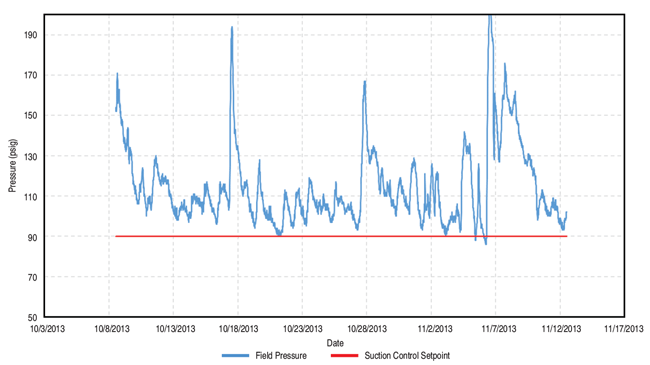
The field pressure, or inlet pressure to the compressor station, often was much higher than the typical control set point used. Data trending showed field pressures to be highly variable, and only occasionally dropped below the suction control set point.
Figure 1A shows a typical field pressure trend at one station equipped with six of the 3606 packages, which was representative of all stations. With the lower suction control set point, efficiency was being lost by compressing the gas at a higher-than-necessary ratio.
Maximizing Capacity
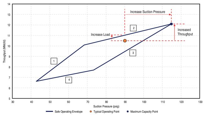
With this knowledge, the modeling effort focused first on illustrating the inefficiencies, and then on developing a procedure to safely adjust compressors to maximize capacity. Figure 1B shows the safe operating envelope for the 3606 package at rated speed and a typical discharge pressure.
The boundaries of the operating envelope are defined as minimum (fully-closed VVCP) and maximum clearance (fully-open VVCP), and rated power (maximum compressor power with site-rated driver power/auxiliary power) and minimum power (minimum compressor power because of driver stability and reliability). In addition to driver site rating and VVCP design volumes, the safe operating envelope may be reduced by rod load, volumetric efficiency, discharge temperature, and other limitations.
The operating envelope shows that the 3606 package could achieve a maximum of 12.1 million cubic feet a day at site-rated power, rated speed and maximum safe suction pressure (minimum compression ratio). Also illustrated in Figure 1B is the typical operating point found near the nominal throughput of 10 MMcf/d for the 3606 package. Thus, with the high field pressure seen at the time, an increase of approximately 2 MMcf/d per compressor could be achieved by adjusting suction control set points and VVCP positions appropriately.
VVCPs can provide infinitely variable clearance and often are installed on cylinders in different stages. If one is not careful with adjusting VVCPs on different stages, load and differential pressures can become imbalanced, leading to equipment damage from excessive rod load, low volumetric efficiency, or high discharge temperature.
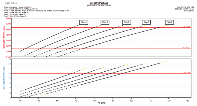
Consequently, the load-step schedule was developed during the modeling as a discreet position of all VVCPs configured to span the range from minimum to maximum clearance in steps of percent load as equal as possible. The percent load increment was targeted at 5-7 percent to give a sufficiently fine step, but not so fine as to require excessive adjustment.
Figure 2 shows the resulting load-step curves for the 3606 packages. The graph is directly from the Ariel Performance Program™, which was used extensively since the majority of the Wattenberg fleet utilized Ariel compressors.
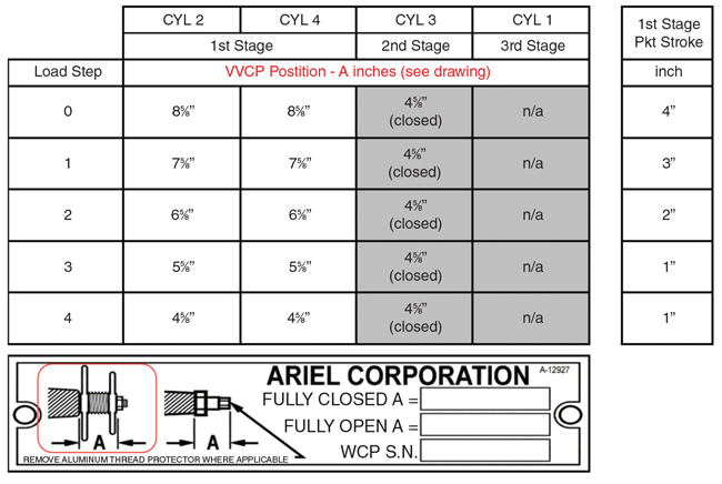
Manually adjusting two-four VVCPs on several like-kind compressors at a station is a physical workout and takes time. Therefore, the load-steps had to be practical for field operators to perform. In addition, the actual VVCP positions for each step had to be easily measured. The measurement tool was presumed to be a tape measure and the position steps were kept at fractional increments of no less than one-eighth of an inch.
Figure 3 shows the resulting load-step schedule for the 3606 packages. Only the first-stage VVCP was adjusted. The second-stage VVCP was kept closed because of the very low volumetric efficiency on first-stage cylinders if the second-stage VVCP was opened. While all the VVCPs could be adjusted to some infinitely fractional position, this would defeat the purpose of a straightforward, repeatable, and robust load-step schedule.
The next part of the procedure was to define the suction pressure control set point. Discharge pressures do vary, although not to the extent seen in field (suction) pressure. When discharge pressure changes, the operating envelope and curves shift, causing the maximum suction pressure point to shift. Therefore, the optimum suction pressure becomes a function of discharge pressure and load step.
The goal of this effort was to develop a procedure to achieve maximum compressor throughput and utilization. The ideal solution was to determine the optimum suction pressure and load step to achieve this goal, and then be able to run the performance model in real time. The Ariel Performance Program has a feature called “multi-run,” which allows load steps to be created and the model to be run over a range of suction and discharge pressures/speeds. The model output at each condition and each load step is written to a comma-separated value (CSV) file. The CSV file became the heart of the optimization tool.
Optimization Tool
With the basic procedure defined, a method was needed to provide operations staff with the recommended suction pressure set point and load step for maximum throughput. The solution was to copy the multi-run CSV file into a spreadsheet and use a “look-up” logic routine to find the optimum configuration.
The development process involved defining a modeling procedure to create performance databases for each compressor. Using the Ariel software’s multi-run feature, each unique compressor was run through a wide range of suction and discharge pressures at maximum operating speed to bracket all foreseeable operating conditions.
Suction pressure was run in 2-psig increments over a 140-psi spread, while discharge pressure was run in 20-psig increments over a 400-psi spread. The actual ranges could be adjusted to match the compressor’s service (low pressure-high pressure, low pressure-intermediate pressure, or intermediate pressure-high pressure), but the range spread and increment was held constant.
This resulted in 1,491 calculated points for each load step. The multi-run CSV file contains all calculated unit parameters (169 parameters for a four-throw unit) for every operating point. Needless to say, this results in a very large database. The three primary parameters of power, throughput, and compressor warning codes were extracted from the CSV file and written into tables. Finally, the tables were combined for the solution look-up. Since this process was applied to a wide variety of compressors with unique configurations, a Microsoft® Access™ database was incorporated to store the various unit model tables.
The Access file also contains several constants for each unique compressor and tag names, and data paths for both input and output parameters in the CygNet™ supervisory control and data acquisition software. The constants required for determining the solution are rated driver power, rated driver speed, auxiliary power, station pressure drop, and limits of the pressure ranges used for each unique compressor database.
Input parameters from CygNet are unit suction pressure, unit discharge pressure, field pressure, current load step, and actual driver load. Output parameters are read from the spreadsheet and passed back to CygNet, and include throughput at current condition, throughput at optimized condition, optimized load step, and optimized suction pressure. Several additional output parameters are passed through the Access file to enhance the presentation of recommendations.
Facilitating Changes
The Access file contains all the variables and model tables for the various compressors, and also has adjustable settings to facilitate changes. This allows the spreadsheet to remain unchanged if compressors are added, deleted or modified. The spreadsheet has a macro programmed to read the data path from the Access file and read/write data from/to CygNet. Once the input data and database are written to the spreadsheet, calculations initiate to both look up data at the current configuration and solve for the optimal condition (i.e., maximum throughput).
One key to this logic is that it will not solve for an unsafe condition by reading the site-rated power and warning codes from the Ariel Performance Program incorporated into the database. Another key that differentiates this method is that it calculates the maximum available suction pressure to use in the look-up. Once the spreadsheet completes the tasks for one compressor and passes the results to CygNet, the process repeats for the next compressor on the list.
To reduce time to complete the process, all like-kind compressors use the same model table, and a new table is not written until a unit with a new compressor configuration is read. The Access file is set up to easily differentiate like-kind compressors and associated tables.
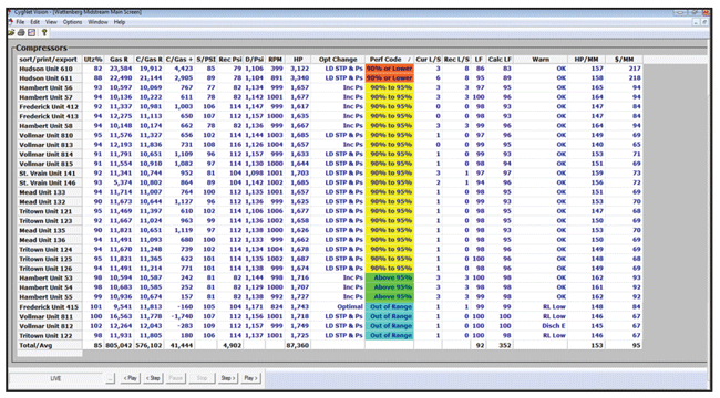
The final piece of the optimization tool is a screen developed in CygNet to allow operations personnel to easily and visually monitor the compressor fleet. It contains several parameters, but the primary ones are compressor utilization (the main parameter to gauge optimization of each compressor), recommended load step, and recommended suction pressure. Utilization is calculated as the throughput at the current configuration divided by the optimal throughput, and a target of 95 percent or greater is desired.
Major supporting parameters are the throughput gain from the current to optimal configuration, the performance code, and warnings of an unsafe operating condition. Figure 4 shows a screen shot of the utilization screen. All parameters can be trended and a playback feature was incorporated for monitoring fleet performance.
Implementation Results
In 2014, Anadarko was increasing production rapidly within the D-J Basin complex, and compression was being installed to the Wattenberg gathering system as fast as possible to keep up. Production growth and compression additions slowed significantly in 2015 with the drop in commodity prices.
It became imperative at that time to reduce capital and operating expenses while increasing efficiency of the fleet to improve profitability. “Energize the base” became the directive, and the optimization tool quickly moved from demonstration into full implementation to help increase production with the existing compression infrastructure.
Immediately after implementing the optimization tool in the Wattenberg system, there was an issue with units tripping on first-stage “differential pressure.” The differential pressure shutdown is an alternative method for rod load protection, as compared with direct calculation of the forces. The allowable differential pressure calculation is a linear equation that returns a maximum discharge pressure for a given suction pressure to keep the rod load at a safe level.
During subsequent investigation of the PLC logic, it was determined that the three-stage compressors were not programmed with the correct coefficients. The units had been relocated from another field where coalbed methane process gas was much lighter than process gas in the Wattenberg Field. The heavier gas affected flow across the valves and the internal cylinder pressure, which in turn, impacted rod load. New coefficients for the differential shutdown equations were derived for the new gas composition and were programmed into the PLCs.
A second issue with differential shutdown also was discovered during this investigation. Because the packager had not installed suction transmitters in the interstages on these units, the prior-stage discharge pressure was being used as the next-stage suction pressure in differential pressure calculations. This reduced accuracy by not considering the pressure drop across the cooler.
Accordingly, a static value for the cooler pressure drop was added to the code to account for the pressure drop, and was based on manual measurements. All 3606 packages were updated to the proper differential shutdown limits and the premature shutdown problem was resolved.
Another limitation was related to the engine drivers. The engines’ factory control system outputs a load factor (percent load), which was being used as the basis to determine whether a unit was fully loaded. A wide spread was seen initially from unit to unit in the load factor versus the calculated percent load from the compressor model.
Anadarko’s maintenance staff found some lingering mechanical issues, but most of the spread was a consequence of how the units were tuned.
Other problems such as fouled spark plugs, plugged precombustion needle valves, and other issues were found during implementation. Minor repairs and tuning were incorporated as part of implementation. One key was tuning with the actual fuel gas heating value to the particular engines at each location. Gains of 50-100 useable horsepower were realized on many units. Once this procedure became part of the implementation process, more consistent performance was achieved and operation at full load became reliable.
There was a concern that active management of compressor VVCPs would allow engines to overload or walk into differential shutdown (rod load) if the field pressure was to rise and the suction set point was not set correctly. The solution was to switch suction control from set point control to load control.
This involved establishing a maximum suction pressure limit, or clamp, for each compressor design. The suction control valve then opened to the maximum suction pressure for a given load step setting–limited by the maximum clamp–to automatically hold the unit at maximum load or throughput condition.
If field pressure was to rise and the load step was not adjusted manually, the suction control valve would throttle back automatically to keep the unit from shutting down on overload or differential pressure. This automated one portion of the recommendations and left only manual adjustment of the VVCPs to meet the utilization target.
Increased Throughput
Once the associated issues were resolved and automatic load control through suction control was incorporated, implementing the optimization tool moved quickly from station to station. The immediate gains in station throughput were significant, with a 10-15 percent increase seen immediately following implementation of 3606 packages at each location.
Once the optimization tool was configured for the majority of Wattenberg compressors, operations settled into a procedure to maintain the increased throughput. The tool runs every 15 minutes, providing the recommended load step and additional data. Manual VVCP adjustments typically are made only when there is a significant change in field conditions.
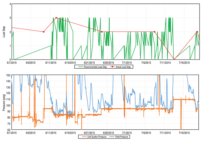
Changes to load step range from every few days to weeks, depending on field pressure dynamics. Figure 5 shows the recommended load step from the utilization tool, current load step, unit suction pressure, and field pressure to illustrate the actual changes made on an example unit.
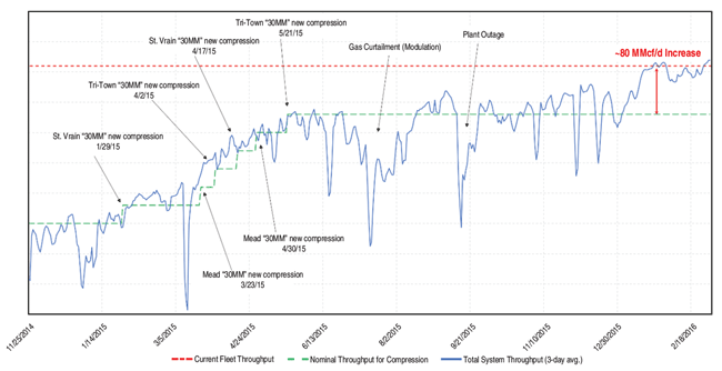
While the gains in throughput on existing compressors did offset some need for additional compression, saving Anadarko significant capital expenditures, new compression also was being installed while the existing fleet was being optimized. The total Wattenberg gathering system throughput through February 2016 is shown in Figure 6, along with the nominal throughput gains from new compression. The approximate throughput gain from the optimization tool is 80 MMcf/d (10 percent) for the total 3606 fleet. The utilization of Wattenberg 3606 compressors increased from approximately 80 to 95 percent.
Several side benefits from using the tool have been realized as well. By closely monitoring various parameters presented on the CygNet screen, operations has learned to identify when mechanical issues are occurring. The engine drivers are tuned more precisely and reliability has improved. Correcting PLC errors and setting other shutdown levels more appropriately has reduced nuisance shutdowns.
Surveying the compressors and building the equipment databases for accurately constructing the models have proven useful for many other applications by engineering, health and safety, operations, maintenance, and other departments. The accurate models created for each compressor also are used extensively for system design and operations purposes.
The optimization tool is being applied to other gathering assets in Anadarko’s portfolio. Enhancements are being evaluated, and include accuracy improvements and additional calculations to monitor operating expense. The methods and procedures employed for the tool also are being looked at to create variations for compressor and driver reliability monitoring and predictive maintenance.
GARY BOURN is a senior staff facilities engineer for Anadarko Petroleum Corporation’s midstream operations services and gas plant engineering group in Denver, supporting compression design and operations for the company’s onshore field developments. He began his career in research and development at Southwest Research Institute, working up to a principal research engineer after 13 years in the natural gas and large engine development group. Bourn then served as a principal reliability engineer at El Paso Corp. and as a compressor engineer at Kinder Morgan before joining Anadarko in 2013. He holds a B.S. in mechanical engineering from Texas Tech University.
MIKE SUTTON is a senior facilities engineer for Anadarko Petroleum’s gas plant engineering group in Denver, working in the Denver-Julesburg Basin. His responsibilities include compressor station optimization, compressor operations support, and in-house gas plant engineering to support operations, construction and design at Anadarko’s processing complex in Fort Lupton, Co. Sutton started his career working for five years with Anadarko’s production team in the Powder River Basin in Wyoming, with the majority of his work focused on electrical design and construction. He holds a B.S. in mechanical engineering and an M.S. in environmental engineering from Montana State University.
For other great articles about exploration, drilling, completions and production, subscribe to The American Oil & Gas Reporter and bookmark www.aogr.com.


