Downhole Vibratory Tools Improve Casing Running In Long-Lateral Wells
By Matthew Warner and Ryan A. Hall
TULSA–One of the defining well construction trends in unconventional resource plays is ever-increasing horizontal lengths to increase recovery efficiency. Advances in drilling technology are redefining lateral length limits while also accelerating spud-to-total depth cycles. However, as lateral lengths have increased, so have the challenges associated with running casing and achieving good cement integrity in long horizontal wells.
The high total-measured-depth to true-vertical-depth ratios seen in many wells present challenges during casing and liner installation, and can become a limiting factor in long-lateral well designs. The primary issue is the high friction associated with extended-reach horizontal well profiles and the absence of adequate vertical pipe weight to overcome frictional forces. This friction can require the operator to apply excessive torque and force to the casing string and completion components, which can damage casing, frac sleeves, swellable packers, etc.
A secondary issue in horizontal wells is cement channeling and poor cement/casing bonding in both the horizontal portion of the intermediate casing string in the curve section and in the lateral liner/casing. Cement integrity is improved by the casing vibrations produced when cement is pumped through a vibratory tool.
To combat these problems in getting casing/liners to bottom, operators increasingly are using downhole vibratory tools similar to those common in horizontal well drilling operations to run casing strings. Downhole vibratory tools break the static friction between the work string and the wellbore or casing. The tool has been used for extended laterals, deviated wellbores, liner hanger systems, cemented and noncemented wells, open-hole packer systems, sleeve-systems, and intermediate casing.
TABLE 1
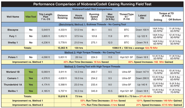
**The following calculation was used to compare casing run times in Table 1:
The average distance rotating for all eight wells (5,201 feet) ÷ the average casing running speed (ft/hr) for each casing method.
Seeking to consistently attain maximum casing depth while improving casing run times in its extended-reach wells, Kaiser-Francis Oil Company conducted an eight-well field study in the Niobrara/Codell play in Wyoming utilizing vibratory casing technology. In this project, a vibratory casing tool was placed in the shoe track between the shoe and collar to run casing in four wells, while casing was run in the other four wells without a vibratory tool. All eight wells were completed with 4½-inch, 13.5-pound, P-110 liner in two-section laterals.
The data show up to a 121 percent average increase in running speed while rotating the liner in the hole using the vibratory casing tool, resulting in as much as an average 55 percent decrease in rig time compared with offset wells (Table 1). Importantly, less torque at higher rotary speeds also was seen on the wells using the vibratory tool.
Downhole Problems
The problems caused by excessive casing-related friction in horizontal wells include:
- Failure to get casing to bottom;
- Excessive time spent running casing (directly impacting operational costs);
- High residual stress left in casing and other downhole components (often causing issues later in the life of the well);
- Damage to casing and sleeve systems caused by rough handling during trip in (including “hammering” casing into the well using the rig blocks); and
- Overtorqued connections during rotation to get casing in hole.
Proper cementing is an integral operation that has significant impact on the completion process and is essential to well longevity. Displacing the drilling mud column with cement can be difficult in long-lateral liner/casing applications because casing typically favors the low side of the wellbore. Casing eccentricity also impedes mud displacement in the narrow side of the annulus, permitting cement channeling and poor cement bonding. Problems associated with achieving a poor cement/casing bond include:
- Compromised well integrity during future operations;
- Failure to isolate weak formations and provide structural support;
- Decreased reservoir isolation and protection;
- Encumbered production optimization efforts such as stimulation treatments;
- Potential exposure to corrosive saline formation water; and
- Fluid/gas migration.
The newest advancement in downhole vibratory casing technology is an expendable tool design that modulates fluid flow. This type of “flow-interrupting” tool utilizes a valve function in which the flow restriction through the tool varies with time. The periodic change in flow restriction causes oscillating back pressure across the tool as fluid is pumped through it.
As a column of fluid travels through the casing string, it encounters this changing flow restriction. When the flow is interrupted by the vibratory tool, the pressure above the tool increases. This pressure increase is caused by both the water hammer effect as the fluid column decelerates and the continued flow of fluid into the casing string by the positive displacement surface pumps.
The increased pressure acts across the hydraulic area of the casing, causing it to elongate. The momentary elongation of the casing breaks static friction and allows for the downward movement of casing. When the flow restriction decreases, fluid pressure above the tool is relieved and the casing contracts to its original length. This process repeats over and over as fluid flows through the tool, causing axial vibration of the casing.
Strong axial vibratory forces reduce the surface tension between the drilling fluid and casing, and between the drilling fluid and formation wall. Axial vibrations also help to break up drilling cutting “bridges,” and allow cuttings and fluids to be pumped out of the wellbore more easily.
Consistent Casing Rotation
The ability to move the casing string during cementing operations is an effective way to counter poorly centralized casing. Pipe movement increases the effective volume of fluid moving in the annulus and supplies a mechanical means for breaking the gel strength of immobilized mud or curing cement that otherwise could not be broken by fluid rheology, flow rates or centralization.
Torque requirements will exceed capacity periodically when cement reaches the lateral section, restricting casing rotation throughout the duration of the cement job. The oscillating axial vibration combats static friction, resulting in less torque and higher rotary speeds to enable consistent casing rotation from commencing cement operations until cement is set.
In addition, the benefits of vibratory casing tools can be observed when well conditions prohibit casing rotation during cementing operations. As the tool modulates flow through it, fluid pulsation is created at the tool’s exit point. The tool’s position near the casing shoe allows the fluid pulses created to be exhausted through the shoe, causing a change in pressure between the end of the casing and the formation, or any object obstructing movement down hole. This changing hydraulic loading at the end of the casing causes an oscillating load between the shoe and the obstruction, creating a “hammer drill” effect that enhances casing installation.
This fluid pulsation breaks fluid channeling and creates uniform flow up the outside of the casing. The vibration of the casing string and fluid pulsation during cementing operations helps to ensure a high quality cement job by reducing voids and channeling, much like vibratory tools used in the construction industry to attain quality concrete with no holes or voids.
Moreover, because there are no moving parts, the tool is very rugged and highly reliable. It contains no elastomeric components, which negates temperature limitations or issues with gas, fluids, chemicals, or nitrified mud. It is highly customizable for various threads and sizes, and has a wide operating range with respect to flow rates as well as mud and cement weights/viscosities. In fact, the maximum flow rate is limited only by how much additional standpipe pressure is available, as well as considerations for the shear values of other completion components in the string.
Niobrara/Codell Field Study
Niobrara/Codell formations present a diverse variety of challenges for casing/liner running operations. Kaiser-Francis challenged itself to advance casing running methods to improve well economics by maximizing efficiency and reducing the costs associated with installing casing. The objective was to implement a viable solution that would decrease run times and minimize the force needed to combat the high drag and friction inherent in horizontal well profiles.
The eight-well project analyzed three methods of running casing for performance. By ensuring that formation characteristics were similar and drilling parameters were kept as close to identical as possible, the disparity in downhole performance can be attributed to the casing installation method used.
Four wells did not use a vibratory casing tool. Casing was run in three wells (Biscayne, Fury 1 and Shelby 1) using buttress threads without a vibratory tool, and in one well (Polara 1) it was run using high-torque semi-flush (SF) threads without a vibratory casing tool. Casing in the other four wells (Worland 1B, Camaro 1, Thunderbird 1A and Malibu 1) utilized high-torque SF threads and vibratory casing tools. A performance comparison of the three methods of running casing illustrates that the four wells in which casing was run with vibratory tools consistently outperformed the four offsets wells that did not use a vibratory tool.
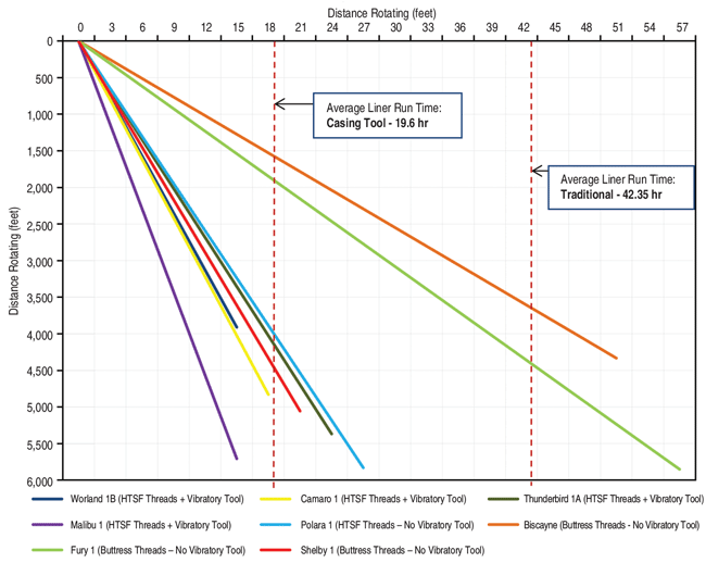
Figure 1 shows the casing running speeds for the eight-well performance analysis. The four wells utilizing the vibratory casing tool appear to form a relatively compact grouping compared with the other wells from the study, further indicating the consistent performance of the downhole vibratory method.
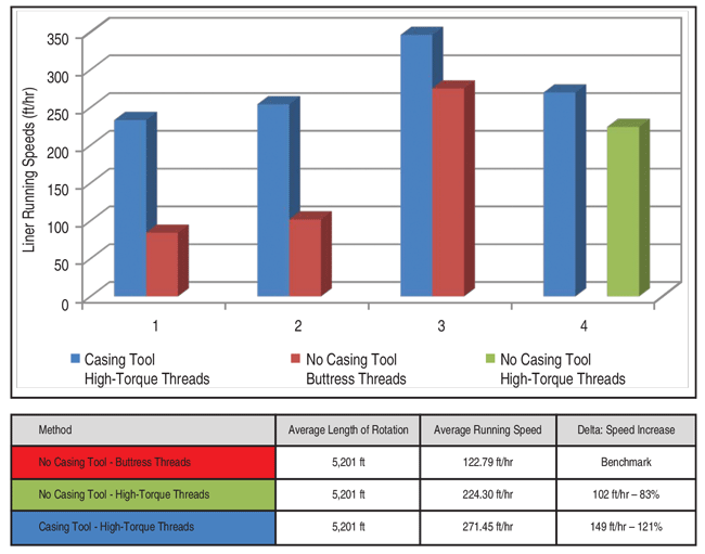
Figure 2 gives a more detailed comparison of the average casing/liner running speeds for the three casing installation methods in this study. The wells using the vibratory tool and high-torque SF casing had a 121 percent average increase in running speed while rotating the liner in the hole, compared with the three wells that used buttress-thread casing and no vibratory tool. Compared with the well using the same high-torque SF casing, but no vibratory tool, the data show a 21 percent average increase in running speed while rotating the liner in the hole on the wells using the vibratory tool.
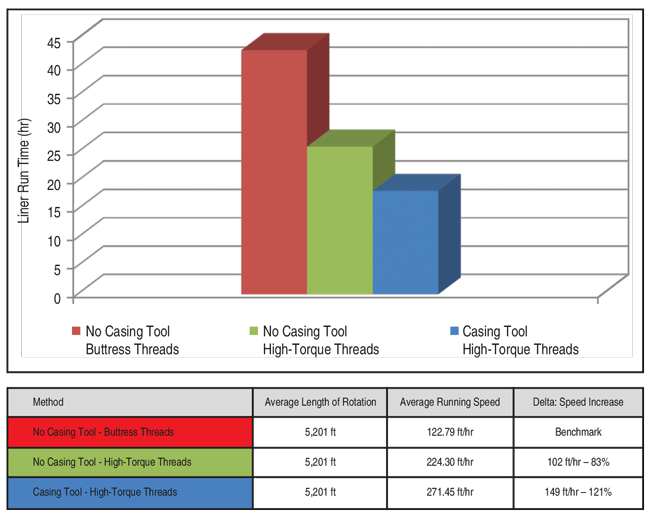
Figure 3 shows the average time required to install casing by the three methods. Using a vibratory tool and high-torque SF casing demonstrated a 55 percent decrease in rig time while rotating the liner in the hole compared with buttress-threads casing and no tool, and a 17 percent decrease compared with high-torque SF casing and no vibratory tool.
As horizontal drilling activity has proliferated in U.S shale plays, the industry has improved greatly its ability to lengthen the horizontal sections of wells. As the Niobrara/Codell field test shows, downhole, vibratory, horizontal casing installation tools are advancing in step with the ongoing progress of extended-reach drilling, significantly increased casing running speeds, and decreased running times while ensuring that casing is run successfully to total depth.
Based on the technology’s ability to enable higher rotary speeds with less rotating torque, it can be inferred that the potential exists to achieve additional cost savings by utilizing vibratory casing tools to prevent overtorqueing threaded connections, to avoid damaging casing and completion equipment, potentially to eliminate the need for high-torque threads in some cases, and to increase recovery efficiency.
MATTHEW WARNER is a drilling engineer at Kaiser-Francis Oil Company, responsible for all aspects of drilling and rig operations, including in the company’s Niobrara/Codell program. He began his career in 2007 as a senior logging engineer at Halliburton Logging Services Asia Ltd., and then served as a directional drilling engineer at Halliburton before joining Kaiser-Francis in 2013. Warner holds a bachelor’s in electrical engineering from the University of Rhode Island.
RYAN A. HALL is corporate business development manager at TTS Drilling Solutions in Oklahoma City. Before joining Thru Tubing Solutions in 2014, he was a regional account manager at Rockwater Energy Solutions. He began his career as a landman at Chisholm Energy LLC and then Chesapeake Energy. Hall holds a B.B.A. in marketing from the University of Central Oklahoma.
For other great articles about exploration, drilling, completions and production, subscribe to The American Oil & Gas Reporter and bookmark www.aogr.com.


