‘Engineered Completions’ Key To Economic Development Of Previously Marginal Elkhorn Field
By Kyle Trainor, Mike Vincent and Ron Finch
FAIRFIELD, N.D.–More than a decade of development has reduced the amount of undrilled acreage remaining in the core of the Bakken/Three Forks play, giving operators strong incentive to identify new locations outside the play’s established boundaries. The large slickwater and hybrid slickwater stimulation treatments utilized in the central portions of the basin may not yield the best performance or be cost-effective to deploy in acreage on the play’s margins, requiring operators to adopt new completion designs and practices.
On the southwestern margin of the Williston Basin in Billings and Golden Valley counties in North Dakota, a 90,000-acre area previously considered marginal is being redelineated through advances in reservoir characterization and improved stimulation practices.
The Elkhorn project area is geologically different than the central basin rocks where the thinner section is more heavily influenced by local subsurface structure and stratigraphy.
The unique geologic, stratigraphic and structural characteristics require a departure from the “bigger is better” approach to fracturing design that has become the norm in the Bakken/Three Forks and other plays (in which more fluid and proppant are pumped into more closely spaced clusters). To enhance well productivity and overall development economics in the Elkhorn project, NP Resources has adapted an engineered completions strategy to tailor customized and right-sized slickwater treatments based on variations in subsurface properties along the lateral.
The initial horizontal wells that have been completed with the engineered treatments are achieving excellent results. In fact, the most recent wells have yielded productivities on the order of 300-400 percent higher than offsets, and their completion costs are substantially lower than wells completed with conventional large slickwater treatments similar to the standard designs in the Bakken/Three Forks.
Unique Geology
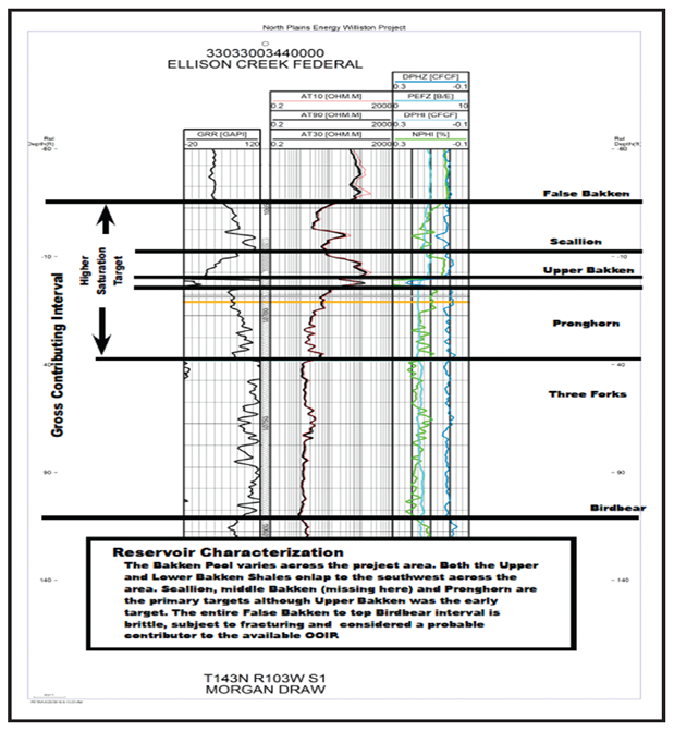
Figure 1 shows the stratigraphic column at Elkhorn, starting at the base of the Lower Lodgepole. The Lodgepole in this area is characterized as a massive carbonate with little or no porosity/permeability that is segmented by thin shale streaks. It is considered a hydrocarbon cap above the Bakken system. Inclusive to the Lodgepole is the “False Bakken” member. It is less prominent on the gamma ray log at Elkhorn than in the basin’s central portion. It also is thicker, ranging from 20 to 40 feet.
At the top of the Bakken pool, the Scallion is a brittle limestone with low matrix porosity and permeability, but it is enhanced by local dolomitization and natural fracturing. In most cases, the Upper Bakken is present, but thinner (two-four feet) and less ductile than in the central basin’s shales. The Bakken/Three Forks target at Elkhorn is defined as a 20-30 foot thick dolomitic siltstone. The lower shale is generally absent, and the two target members sit in direct contact, where the Middle Bakken may be better defined as a group of dolomitic clastics atop dolomitic siltstones. The Lower Three Forks shows pockets of oil saturation that are segregated vertically by thinly bedded shales and cemented carbonates.
Elkhorn’s structural diversity also is unlike the classic Bakken petroleum system. Influenced heavily by the Beaver Creek Anticline, large through-going vertical and subvertical natural fractures are routine in the central basin. These tectonic fractures play a significant role in system mechanics and reservoir deliverability, as evidenced by production from legacy unstimulated vertical and horizontal wells. Legacy unstimulated open-hole horizontals did not reliably recover incremental reserves compared with the vertical wells, but did achieve more predictable production with a narrower distribution of production rates and estimated ultimate recoveries, reinforcing the interpretation of productive interconnected natural fractures in the Elkhorn area.
Legacy Wells
Elkhorn development began in the early 1960s with vertical penetrations targeting various intervals, including the Bakken and Three Forks. The first horizontal completions targeting the Bakken/Three Forks were drilled in the 1980-90s, and were primarily short uncemented and unstimulated laterals completed with pre-perforated or slotted liners. A second generation of horizontal wells was completed in the project area between 2010 and 2014. They consisted of 10,000-foot laterals completed with uncemented liners, external packers and sliding sleeves. The second-generation wells were hydraulically fractured primarily using a cross-linked fluid system and 3 million-4 million pounds of 40/70- and 20/40-mesh white sand in 10-35 stages.
The unstimulated wells–both vertical and horizontal–produce very little water, with oil cuts typically exceeding 90 percent. In contrast, second-generation horizontals that have been hydraulically fractured generally yield maximum oil cuts of 60 percent, suggesting fracture growth into water-bearing strata above or below the lateral. Moreover, the second-generation horizontals are forecast to achieve EURs approximately equal to the unstimulated first-generation horizontals.
The stimulation histories of second-generation child wells show a correlation between the quality of the treatment execution and the producing oil cut. In particular, wells with the lowest oil cuts had a higher number of pressure increases during treatment and often had unintended screen-outs. One explanation is that near-wellbore proppant bridging and increased net pressure created undesired fracture height growth into surrounding water-bearing strata. An alternate mechanism is that proppant bridging redirected fluid injection into a localized portion of a stage rather than even distribution into multiple fractures, resulting in excessive height.
With a thin pay interval bounded by undesirable water hazards, NP Resources elected to design completions with tailored propped fracture spacing/sizing while honoring the vertical height growth constraints. Optimizing perforation cluster efficiency is critical using a combination of careful stage placement, engineered perforation locations within similarly stressed rock, aggressive extreme limited-entry perforating techniques and tailored proppant placement throughout the lateral.
Early Experiments
The legacy wellbores offered a unique opportunity to observe how hydraulically induced fractures may distribute without mechanical isolation. A refrac was pumped in a 3,600-foot uncemented lateral that had been completed in 2008 with external water swellable packers and eight sliding sleeves. The original stimulation had placed a modest 837,000 pounds of proppant in 13,029 barrels of cross-linked fluid. After cleaning out the well to total depth with coiled tubing, it was restimulated with 1 million pounds of proppant and 48,000 barrels of slickwater in a bullhead injection.
A warm-back survey indicated that the unconstrained restimulation injection resulted in 30 discrete injection points with a median spacing of 110 feet (ranging between 50 and 400 feet) and confirmed that slurry entered all eight sleeves in the open hole. Although a bullhead restimulation is not equivalent to a staged completion, the results suggested that a fracture density greater than one per 110 feet (or two to three fractures a stage) may require isolation with cemented liners and additional diversion into a higher density of perf clusters.
Recognizing the presence of productive natural fractures in the project area, it was unclear how well these natural fractures interconnected over the large geographic area, or what storage capacity they offered. NP Resources initially attempted to contact and preserve these features with an uncemented lateral. Well 1 was completed using external water-swellable packers and three clusters per stage in a plug-and-perf sequence. No attempt was made to gather data in the lateral, adjust proppant mass by stage or deploy a limited-entry perforating scheme. The stimulation consisted of 200,000 barrels of slickwater and 5.6 million pounds of proppant with nearly even size distribution between the 35 stages. The early-time production response indicated a meaningful productivity improvement using slickwater and a larger proppant mass and fluid volume compared with legacy completions, but the water cut was significantly higher than offsets stimulated with smaller treatments.
Systematic Changes
Four months later, Well 2 was completed adjacent to Well 1. A cemented completion was specified to evaluate whether controlled fracture fluid distribution would result in a lower water cut and improved oil productivity. The number of stages was identical and treatment volumes were similar to allow its production to be compared with that of Well 1. Although the wells are nominally parallel, the distances between them along the dominant fracture azimuth are 1,449-1,739 feet.
Well 2 was logged with a pulse neutron tool to characterize the lateral prior to cementing the 4½-inch production liner. Then, Well 1 was shut in during Well 2’s stimulation, effectively leaving a downhole pressure gauge available to monitor the intensity and arrival times of the frac hits.
The treatment design on Well 2 incorporated systematic changes in the number of clusters (six versus three per stage), injection rates, and the use of degradable diverters and degradable balls. Frac hit arrival times and magnitudes were observed to evaluate diversion effectiveness. The apparent transit speed of frac fluid between the wells was analyzed to determine whether six perforation clusters would encourage the initiation of more fractures in each stage (thereby retarding fracture extension). All other factors being equal, frac extension from a stage that uniformly distributes frac fluid between six clusters instead of three should take twice as long to reach the observation well.
In addition to pressure observations, the fluids injected in Well 2 were tagged with unique oil and water chemical tracers in each of the 35 stages. Well 1 was returned to production after stimulating Well 2, and water and oil were sampled and analyzed periodically during the first 33 days to determine the degree of communication between the wellbores.
The initial post-frac water sample was collected from Well 1 after it produced only 65 barrels of flowback and showed significant concentrations of water-soluble tracer from 31 of the 35 stages in Well 2, indicating that well-to-well fluid transfer had occurred in most stages during or immediately following treatment. Only 19 of the oil-soluble tracers were identified in the initially collected sample, but during the first month of production, 34 of the water-soluble tracers and 31 of the oil-soluble tracers were recovered in significant quantities in Well 1.
The magnitude of the pressure incursions in Well 1 were small (less than 245 psi), and were observed within 27-106 minutes after initiating pumping on Well 2. However, based on the observations of water-soluble tracer in the adjacent wellbore immediately after stimulation, the pressure events were interpreted to document true fluid transfer and not poroelastic stress shadowing. The data showed pressure increases on stages 5-35, and low-magnitude pressure increases less than 6 psi on stages one-four.
To consider these variations, the arrival times were converted into an apparent fluid transit velocity normalized to the average fracturing rate of 52.4 barrels a minute. The analysis showed a trend to larger magnitude and more rapid interference on later stages (suggesting a cumulative effect from previous stimulation treatments, perhaps compounded by geologic or structural variations along the wellbore), but no statistically meaningful differences between stages completed with six versus three clusters, regardless of whether diversion material was used. Analyses of water- and oil-soluble tracers recovered from Well 2 also showed no meaningful difference in tracer recovery, regardless of perforation or diversion strategy.
Frac fluid injection rates had been varied in specific stages during treatment. The data showed that stages impacted the adjacent well after a similar cumulative volume of fluid was pumped, regardless of injection rate. This suggests that increased injection rates did not distribute fluid successfully into a greater number of fractures. The data also suggest that altering the injecting rates between 44 and 59 bbl/minute did not appreciably affect the undesirable height growth.
Created fracture half-lengths developed rapidly, as documented with both pressure monitoring and tracers. But while in-zone frac hits were observed at distances in excess of 1,700 feet along the perceived fracture plane, there were no observable frac hits in legacy uncemented laterals in the overlaying Madison or underlying Nisku. The anhydrites in the bottom section of the Three Forks appear to be a competent frac barrier to downward growth into the Nisku in the Elkhorn area. However, the anhydrites appear below the depth at which oil saturations in the Three Forks begin to precipitously decline; therefore, even minor downward growth may increase water cuts. Likewise, the carbonates and alternating shale streaks in the Lodgepole appear to provide a competent barrier to upward fracture growth in this region of the field.
These interpretations of acceptable height containment but poor diversion using contemporary perorating strategies and degradable diverters encouraged further investigation into stress variations along the lateral, and eventually led to more aggressive diversion schemes to generate 1,500-2,000 psi of pressure differential across the perforations.
Stress Variability
In Well 2, the lateral’s relative stress differences were characterized with a dipole sonic log deployed on a wireline tractor. Refinements to data capture and interpretation were made on subsequent wells using stress-sensing equipment run on the drillstring. Stress data captured during drilling were integrated with minerology data captured from the pulse neutron tool to refine the stress model in the presence of changing minerology.
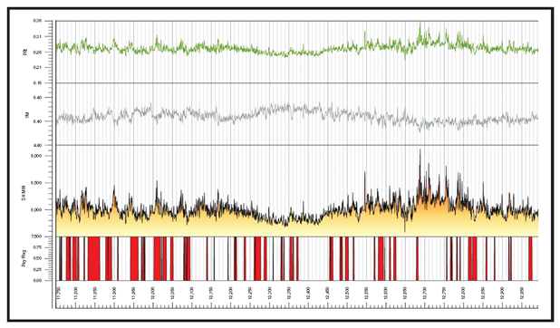
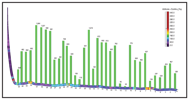
Variations in stress were measured as having differences of greater than 800 psi in 200-400 foot intervals (Figure 2). A 40-50 percent variation in stress relative to the applied differential presents a significant challenge. Therefore, the laterals were compartmentalized carefully into stages based on formation stress rather than uniform stage lengths.
For example, if rock stresses were consistent over a 500-foot interval, the number of clusters and limited-entry perforations were adjusted to cover the interval and generate 1,500-2,000 psi of perforation friction at a rate and pressure achievable by the frac equipment. Likewise, if the rock stresses were variable over a 500-foot interval, it was compartmentalized into smaller stage lengths.
The average stage length in portions of laterals with consistent rock stresses range between 200 and 300 feet. However, by applying a perforating scheme adapted to the rock stress, the number of wireline runs can be kept to a minimum while maximizing cluster efficiencies. Significant efficiencies and cost savings can be achieved in the Elkhorn project area utilizing an engineered and customized staging/perforating strategy based on the wellbore stresses. Aggressive efforts are made to distribute fluid and proppant evenly into a large number of clusters to:
- Minimize undesirable height growth into the water-bearing strata above and below the target landing depth;
- Compensate for low fracture conductivity and overflushed/degrading conductivity over time;
- Preserve infill drilling locations and optimize full field development (reduce parent-child well competition by controlling fracture dimensions); and
- Reduce undrained pockets of stranded oil (increase recovery factor of stimulated area).
Perforating Strategy
Several perforating strategies are being incorporated at Elkhorn to improve the distribution of frac fluid and proppants, including:
- Extreme limited-entry perforating that targets a range of 1,500-2,000 psi of perforation friction to increase the percentage of perforations that break down and accept slurry;
- Uniform hole size and depth of penetration to improve breakdown efficiency; and
- Oriented perforating with 0- and 180-degree phasing to better align with the fracture plane and reduce near-wellbore friction/tortuosity.
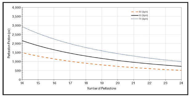
Each stage has seven perf clusters (18-21 total perforations) and entry point spacing is approximately 40 feet between clusters, with two-four holes in a cluster. Figure 3 shows the perf friction generated as a function of rate. After adopting this extreme limited-entry approach in wells 5, 6 and 7, step-rate tests were run at the beginning and at the end of every other stage, offering a quantifiable measure of the number of open perforations.
Cluster efficiency measured at the start of the stimulation routinely exceeded 90 percent. Step-rate tests in wells 5-7 showed near-wellbore friction ranging from 696 to 1,744 psi, with an average of 1,100 psi. The average perf friction was 822 psi and the number of holes open was 19, based on the start-of-treatment step-down data. This contrasts with earlier wells 3 and 4, which employed a more conventional limited-entry scheme with 60-degree phasing, standard perforating charges, and six-eight clusters with 36-38 perforations a stage. Wells 3 and 4 each had a much lower average cluster efficiency (50 percent) at the start of each stage, reinforcing the interpretation of poor diversion efficiency in similarly perforated Well 2.
Treatment responses and step-rate test data suggest that the extreme limited-entry perforation stages are more sensitive to minor changes in maximum proppant concentration, implying that narrower fracture apertures are likely to develop because of the cumulative stress shadow effect of numerous, closely-spaced fractures initiating simultaneously.
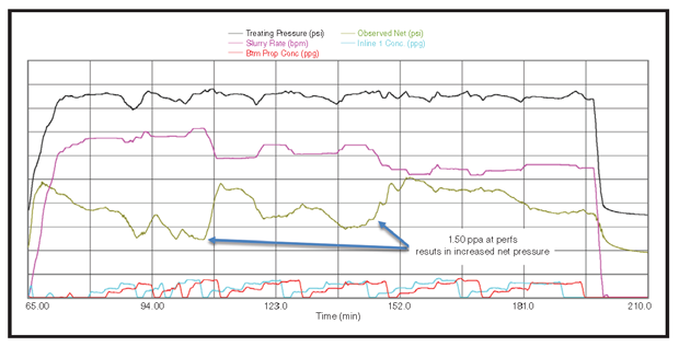
In the example shown in Figure 4, a change in proppant concentration from 1.25 to 1.50 pounds added per gallon was enough to generate a meaningful net pressure change. Step-rate tests run during this and other stages with similar responses showed high start-of-job cluster efficiency prior to pumping proppant and a reduced number of open perforations during the final step-rate test, indicating that proppant slugs were sanding off or screening out some of the fractures.
Field observations indicate that aggressively placed cyclic proppant ramps, combined with extreme limited-entry perforating, can achieve diversion effectively while placing a desirable material in the fracture and avoiding concerns regarding degradation times associated with the previously utilized degradable diverters.
Completion Design
The wellbore and stimulation procedures continue to evolve based on the observations and lessons. The current wellbore architecture and completion design at Elkhorn consist of a 10,000-foot lateral completed with a 4½-inch cemented liner. The slickwater treatment is pumped down the 7-inch intermediate casing or 4½-inch tieback string at 50-70 bbl/minute, depending on a given stage’s wellbore and near-wellbore friction. A total of 24-35 stages is specified, consisting of 6-15 clusters a stage based on stress variations along the lateral.
The pump schedule consists of four-six cyclic proppant ramps of alternating 100-mesh uncoated sand and 40/70-mesh curable resin-coated sand at a maximum concentration of 1.25-1.50 ppa. During treatment, the effect of maximum bottom-hole proppant concentration on observed net pressure is used to increase or decrease proppant concentration to improve the amount of diversion after the first 40/70 cycle. This helps achieve more even proppant distribution throughout the stage and reduces difficulties in pumping the full mass of the stage in the event the amount of diversion forces a significant rate drop.
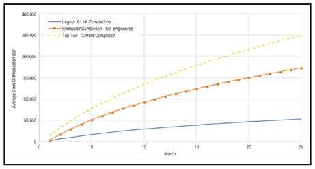
As shown in Figure 5, the three wells completed at Elkhorn using this newest approach are as much as four times more productive than the second-generation horizontal wells completed in 2010-14. Moving from a cross-linked fluid to slickwater with more stages and increased fluid/proppant volumes generated a 250 percent base uplift. Extreme limited-entry perforating and an increased focus on stage placement tailored to the lateral’s variability has yielded an additional 150 percent improvement. This production uplift and the efficient allocation of a smaller capital investment translate to a meaningful return on investment for acreage once considered on the economic fringe.
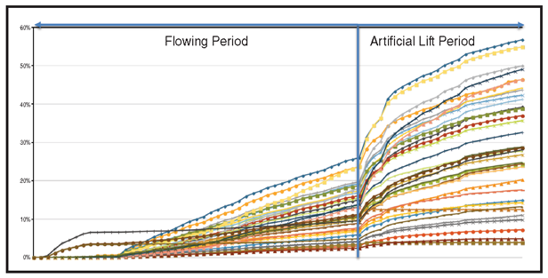
Unique oil and water chemical tracers run in each stage indicate that the most productive wells achieve a consistent production profile throughout the lateral (Figure 6). These highly productive wells vary in the cumulative recovery of chemical tracer along the entirety of the lateral, but are not dominated by one or two stages that significantly outproduce other stages. This cumulative productivity monitored in long-term chemical tracer surveys has been sustained through the flowing periods and into production on artificial lift (Figure 7).
Because these wells are equipped with ESPs and downhole pressure gauges, it is possible to accurately normalize well production for the applied drawdown. The uplift in the productivity of total fluid normalized by drawdown suggests the completions have sustained a greater contact area with the reservoir compared with legacy completions, despite accelerating production with high-volume artificial lift.
The insights captured in the Elkhorn project have proven significant upside potential in an area outside the central Bakken/Three Forks development. Understanding changes in regional reservoir characteristics has become the foundation of the engineered completions approach, with reservoir variations dictating the customization necessary to improve oil recovery and development economics substantially. While initial wells completed with this approach are demonstrating highly compelling results, the treatment designs at the Elkhorn continue to evolve and additional improvements are anticipated that will drive further productivity and economic benefits.

KYLE TRAINOR is a reservoir and completions engineer at NP Resources, with experience in various basins across the Rocky Mountain region. His principal areas of experience include reservoir evaluation in unconventional oil and gas plays, and hydraulic fracture optimization through the use of reservoir and fracture simulation. Before joining NP Resources, Trainor worked as a reservoir and completions engineer for Whiting Petroleum and Kodiak Oil & Gas. He holds a B.S. in petroleum engineering from the Colorado School of Mines.

MIKE VINCENT is a consulting engineer with more than 25 years of experience in economically optimizing hydraulic fractures. After beginning his career at Amoco, ARCO and Carbo, Vincent started Insight Consulting in 1996, specializing in fracture design and reservoir analyses. A former Society of Petroleum Engineers distinguished lecturer, Vincent has served as a technical editor for three SPE journals and is a frequent university lecturer and instructor of fracture design and optimization schools. He holds a B.S. in petroleum engineering from the Colorado School of Mines.

RON FINCH is director of completion operations and reservoir engineering at PetroPro Engineering. He has more than three decades of experience in reservoir, production and completion engineering operations. Finch’s expertise includes evaluating, designing and executing hydraulic fracturing treatments, and optimizing completion results by integrating reservoir properties with stimulation characterization. He holds a B.S. in chemical engineering from the University of Colorado.
For other great articles about exploration, drilling, completions and production, subscribe to The American Oil & Gas Reporter and bookmark www.aogr.com.


