


Microproppant Offers Lasting Benefits
By Carl T. Montgomery, Eduard Siebrits and William E. Strobel
In unconventional plays, only a third of the fractures created during hydraulic fracturing contain proppant. This striking observation, which comes from overcoring and numerical modeling, helps explain why shale wells’ production generally declines 60%-70% in the first year. The unpropped fractures allow some hydrocarbons to flow through at first, but their capacity quickly diminishes as they close.
Ideally, every fracture would receive proppant. To get as close as possible to achieving that goal, the industry is pumping more fluid and proppant for every foot of lateral, shortening stage lengths and tightening cluster spacing. Many of the smartest completion engineers also augment traditional proppant sizes by including spherical microproppants, which are small enough to access sections of a propagating hydraulic fracture that normal proppants cannot.
On average, adding microproppants increases a well’s production by more than 10%. In the Permian Basin, we have seen uplifts beyond 20%. These results translate into millions of dollars in extra revenue over a five-year period, a boost that can significantly reduce a well’s breakeven costs.
The uplifts seen in the field validate predictions from simulations and laboratory tests. Simulations run on an industry-leading planar hydraulic fracturing simulator suggest that microproppants increase the propped fracture surface area by at least 9% compared with 40/70 proppant alone. Laboratory tests confirm that the fracture width of the extra propped area is sufficiently conductive for shale oil and gas production.
Small But Powerful
There are multiple types of microproppants, much like regular proppants. Based on field testing, an effective microproppant must have a median size in the 25 micron range (500 mesh). That is much smaller than the microproppants more commonly in use today, which are generally 75 microns or larger.
Shape is another critical factor for effectiveness: the microproppants should be spherical to create hydrocarbon conductivity. Angular microproppants can pack together like bricks and hinder hydrocarbons’ flow.
Beyond small size and a spherical shape, other factors influence microproppants’ effectiveness. Field results also indicate that microproppants should be:
- Strong (with an unconfined compressive strength of 60,000 psi);
- Sufficiently stiff (meaning the ratio of shale rock to proppant Young’s moduli exceeds 0.2); and
- Thermally stable (up to 2,000 degrees Celsius).
To maximize the return on investment, microproppants should be targeted at formations with limited proppant embedment issues and sufficiently low permeability. With that in mind, we recommend considering them in shale formations with Young’s moduli beyond 2.5 million psi, and permeabilities less than 5,000 nanodarcys (thereby ensuring a dimensionless fracture conductivity above two, for an assumed 100-foot-long hydraulic fracture). Independent laboratory conductivity tests validate that spherical microproppants meet this threshold, using kerosene as the producing fluid in the test.
Delaware Basin Case Study
These are not difficult conditions to meet. In fact, microproppant has an impressive and growing track record in plays across the United States. As an example, consider a field case from the Delaware Basin, where an operator used a spherical microproppant on two laterals (colored magenta in Figure 1) and regular sand on two other laterals (colored purple). All four wells targeted the Wolfcamp A interval and were completed in 2019.
FIGURE 1
Delaware Basin Laterals Containing Microproppant (magenta) vs. Regular Sand (purple)
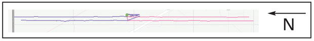
TABLE 1
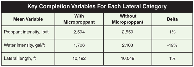
FIGURE 2
Production Uplift at Key Points From Microproppant
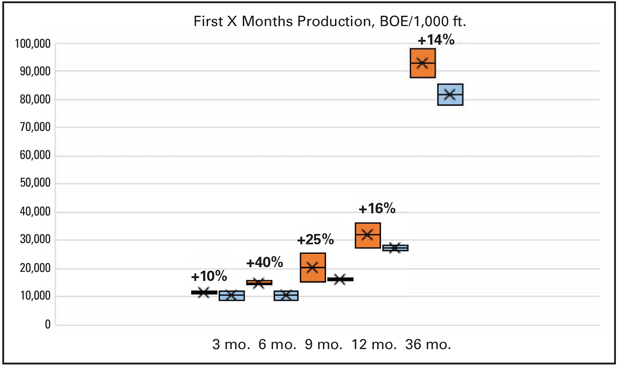
Table 1 shows the mean proppant and water intensities, as well as the mean lateral length, for each category of lateral. In this field case, the micropropped wells used a similar amount of proppant and less water.
Figure 2 is a box-and-whiskers plot of the wells’ production (from Enverus’ PRISM software) at time intervals of three, six, nine, 12 and 36 months. The laterals containing spherical microproppant (orange) have produced substantially more hydrocarbons than the regular ones (blue). At the three-year mark, the micropropped wells had delivered 14% more than their counterparts.
This uplift began showing up early in the wells’ life, with the micropropped wells demonstrating 40% more production at six months and 25% more at nine months. These early results mirror numerous other case histories showing that microproppant delivers a rapid return on investment.
FIGURE 3
Pressure vs. Time for a Stage Containing Microproppant
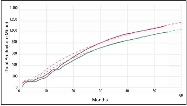
For a longer view, look at Figure 3, which shows the cumulative mean production for each category of completion for the first five years. The solid magenta line tracks the true production for the micropropped wells, with the green line below showing the regular wells’ production and the dashed lines indicating predictions for their respective categories. Conducting type curve analysis and exercising the single-well production model available in Enverus’ PRISM software suggest that the laterals containing spherical microproppant will have slightly lower breakeven costs and generate $5.2 million in additional revenue across five years.
The micropropped laterals also have flatter decline curves, presumably because the smaller propped fissures continue to contribute to production.
Other Benefits
In addition to improving the effective propped area, observations show that spherical microproppants provide four other benefits. Specifically, they:
- Scour the near-wellbore area, which can reduce the pump pressures required to put proppant away;
- Act like far-field diverters, preventing interactions between parent and child wells;
- Improve perforation efficiency; and
- Reduce convergent flow effects.
The scouring and far-field diversion effects are supported by field data. Figure 4 shows a treating plot from one stage in a 44-stage, six-cluster fracture performed in the Delaware Basin. The red line is the surface treating pressure, while the green line is the pump rate. Because the treating string is loaded with the same proppant concentration and the pump rate is almost constant, the surface treating pressure should be a fair representation of downhole pressure behavior. The plot highlights when the microproppant arrives at the perforations and when it is fully displaced.
FIGURE 4
Perforation Efficiency for Stages With and Without Microproppant
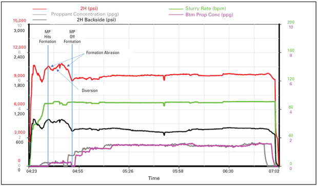
When the spherical microproppant hits the formation, there is a drop in treating pressure, followed by an increase, and then another sharp drop. The initial pressure drop likely results from near-wellbore rock abrasion. The subsequent pressure increase is attributed to bridging and diversion into one or several of the clusters or secondary fractures. Finally, the second sharp drop comes from additional rock abrasion in the new clusters or fractures that were opened by the increased pressure.
The pressure dip in the middle of the micropropped stage appears to be a change in pump rate rather than a reservoir response. Outside that, most of the 44 stages in this well exhibited a similar pattern.
FIGURE 5
Perforation Efficiency for Stages With and Without Microproppant
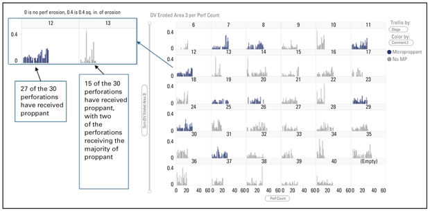
Field tests also validate spherical microproppants’ ability to increase perforation efficiency. Figure 5 shows acoustic imaging results for a 40-stage perforation efficiency test completed in the Eagle Ford. The dark blue stages received spherical microproppant, while the light gray stages did not. Stages 12 and 13 are enlarged for better viewing. They illustrate the clear pattern that stages with microproppant have much better placement effectiveness than those that only received 100 mesh sand.
One mechanism for the stronger placement relates to inertia. Because of their small size, microproppants have one ninth the inertia of 100 mesh and 1/52 the inertia of 40/70 mesh, meaning it is much easier for them to change direction. The small diameter also makes microproppant much easier for the frac fluid to carry. They are less prone to focusing away from the fracture walls than larger proppant, tending instead to remain dispersed across the flow channel.
In any case, spherical microproppants’ combination of directional flexibility and low settling velocity means the proppant flows into the perforation and opens any wellbore restrictions. If a microproppant encounters any jogs along the fracture path as it continues onward, it can navigate past them more easily rather than settling out, enabling it to reach areas that traditional proppant alone will leave untouched.
Microproppants also may improve production by mitigating the near-wellbore pressure drop associated with convergent flow. As the spherical microproppants erode the near-wellbore rock, they create more conductive channels around the borehole, theoretically reducing the near-wellbore “choke” caused by the fracture adjusting to far-field stresses as it moves away from the hoop stresses. It’s difficult to know how significant this effect is, but it likely explains at least some of the production uplift operators are seeing in the field.
Easy Implementation
One of the beauties of microproppant is that it is easy to handle, especially if operators use silica-free versions that eliminate any silicious dust hazard. The production enhancer is manufactured as a dry solid, then pumped as a slurry. The slurry composition varies, but it generally is an aqueous solution of a viscosifying agent and microproppant. The microproppant concentration target is 65% by weight of solution, which translates into roughly 8.2 pounds of microproppant for every gallon of slurry.
The microproppant slurry is viscous and develops a static gel strength. The density generally falls between 13.5 and 13.6 pounds per gallon.
Totes or ISO tanks are used to transport the slurry to a well location. In the field, the slurry flows easily out of the tanks through a three-inch valve and hose that is rigged up to a centrifugal pump to provide boost pressure. The pump sends the slurry into a missile manifold, where it is proportioned in the frac fluid by varying the microproppant concentration added by slurry to the total fluid rate. The microproppant can be added into the pad at concentrations as low as 0.25 pounds per gallon, but to minimize water usage, we now see concentrations as high as 0.7 pounds per gallon.
Instead of pumping the microproppant slurry from an ISO tank or tote with a centrifugal pump, some companies introduce microproppant into a well by pulling the slurry from the tank or container with the blender’s suction pump and adding the microproppant at design concentration on the fly with the rest of the incoming water from the frac tanks. The slurry can be pumped by every pump or by a bank of pumps designated for pumping proppant during a given stage or frac. Another alternative that may reduce transportation and product costs is to add microproppant as a dry material to the sand hopper through a silo or box system.
However it is deployed, microproppant frequently offers attractive returns. In addition to increasing production from multiple intervals in the Delaware Basin, microproppant has excelled in field tests in the Midland Basin, Utica, SCOOP, Barnett, Marcellus, Bakken and Eagle Ford. It is proof that smart proppant choices, along with the right chemistry, can escalate well performance, accelerate payback periods and improve long-term production.

CARL T. MONTGOMERY is a senior engineer at Tulsa-based NSI Technologies LLC. As a pioneer in completion techniques for unconventional wells, Montgomery specializes in all areas of stimulation, cementing, sand management, conformance control, perforating and formation damage. A former Society of Petroleum Engineers’ distinguished lecturer, Montgomery has been recognized with the SPE Engineer of the Year Award for drilling and completions, the ConocoPhillips Lifetime Achievement Award, and membership in the Legends of Hydraulic Fracturing group. He holds a B.S. in biochemistry from Colorado State University and an M.S. in biochemistry from Ball State University.

EDUARD SIEBRITS is a consultant to Zeeospheres Ceramics LLC. During his 29-year career in the upstream service sector, he has built expertise in developing and applying hydraulic fracturing simulators, published several articles, and earned numerous patents. He has experience in directing geomechanics projects and managing rock and fluid testing laboratories, including time as vice president of TerraTek Inc. Most recently, Siebrits has used multiple data analytics techniques to separately quantify the effects of surfactant-solvent chemistry and microproppant on oil and gas production. He holds a B.S. and an M.S. in civil engineering from the University of Cape Town, and a Ph.D. in geoengineering from the University of Minnesota.

WILLIAM E. STROBEL is president of Zeeospheres Ceramics LLC in Lockport, La., which manufactures microproppant. He has served as chief executive officer or president of several technology and public companies, including a Fortune 500 company. During his career, Strobel has identified, negotiated and integrated six acquisitions. He has substantial experience in finance, manufacturing, sales, marketing, product development and business planning. Strobel holds a B.B.A. from the University of Texas at Austin and an M.B.A. from California State University at Fullerton, and he is a graduate of the executive development program at the Wharton School of Business.
For other great articles about exploration, drilling, completions and production, subscribe to The American Oil & Gas Reporter and bookmark www.aogr.com.

