Cameras Enhance NGL Recoveries
By Paul Stockwell
When liquids make it out of gas processing plants and into export gas lines, the ultimate result can be millions of dollars in lost revenue and serious safety risks. These risks range from premature failure of compressor seals to corrosion that can cause pipelines to rupture if it goes unnoticed.
To detect liquids in dry gas streams, gas processors monitor water and hydrocarbon dewpoints. Unfortunately, data from new camera systems has revealed that these monitors frequently miss fault conditions and allow liquids to pass through custody transfer points without tripping alarms. In many cases, gas processors are unknowingly losing Btus in the form of natural gas liquids.
The key to preventing these losses is effective phase separation. Numerous observations have shown that sales quality gas often contains liquids unless phase separation is performed at a high level and at a low temperature. Thorough separation at the front end of the plant is equally vital, as liquid carryover is the leading cause of failures in gas processing that result in lost production and excess chemical consumption.
Because phase separation and filtration systems protect critical equipment, these systems should be judged based on the contamination they allow through rather than the contamination they stop. By augmenting existing moisture measurement systems using permanent cameras, gas processors now have a way to gain real-time information on their separators’ performance.
In addition to enabling processors to spot and quickly address any liquid carryover events, this information allows plant engineers to balance processing trains to minimize carryover and investigate any differences. Then they can take evidence-based action to improve phase separation, minimize foaming and comply with tariffs. These improvements boost production, reduce costs and improve safety.
Visual Insights
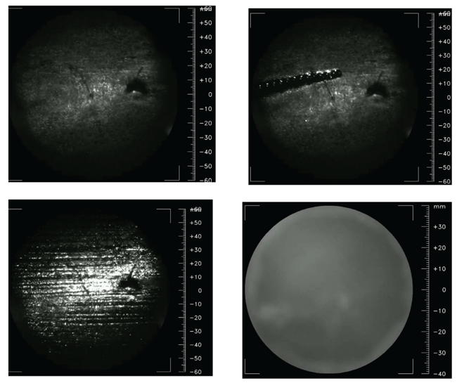
The process cameras are mounted vertically on a pipeline and look at the pipeline floor by illuminating and imaging through an isolation valve. This setup uses existing tapping points. The camera’s images provide a plan view of the pipeline floor, with features on that floor acting as a frame of reference.
As Figure 1 shows, this view frequently reveals liquid streams, solids and mist flows in gas that other indicators suggest is dry. The images in Figure 1 come from real-world installations in a 36-inch pipeline with various contamination flows. Gas pressure was 920 psi and gas flow velocity was around 15 feet a second. The top left shows dry gas flow, while the top right shows stratified flow of compressor oil with a surprising worm-like shape. The bottom left is a stratified flow of condensate in many small streams, and the bottom right is mist flow so severe it completely obscures the pipeline’s features. Stratified flow and mist flow can occur independently and simultaneously.
These still shots do not convey as much information as the videos from which they were taken. In a live feed, aerosols travel at, or very close to, the gas velocity, while stratified flows at the bottom of the pipe travel much slower because they are moving just by the friction with the gas stream above them. Several factors influence stratified flows’ speed, including density, viscosity, gas flow rate, pressure and surface roughness.
By watching live feeds from process cameras, control rooms frequently notice liquid streams present when no other alarms have been activated.
Wet gas goes undetected by gas chromatographs and other analyzers because of the origin of the samples they see. Standards by both the American Petroleum Institute and GPA Midstream recommend using a stabbing probe or quill to remove gas samples from the middle of the pipeline rather than the wall, where liquids and other contaminants tend to be. This necessary precaution extends equipment life, but it means the sample the analyzer examines lacks any liquids present in the pipeline, such as glycol, amine and NGLs.
Since gas analyzers can only report on the portion of fluid they are presented with, measurements made at custody transfer points often have huge errors in calorific values when two-phase flow is occurring. In fact, these errors frequently exceed 30 Btu. Such inaccurate measurements can cost gas processors billions of dollars a year.
In many cases, gas samples are reported as dry and operators are unaware mixed-phase flow is occurring. The cameras can alert operators automatically when mixed-phase flow begins and validate analyzer measurements during single-phase flow.
Empowering Plants
In addition to preventing valuable liquids from leaving gas processing plants, live video feeds and associated data can help plants operate more efficiently by providing a useful new metric for evaluating phase separation systems and other parts of the gas treatment process.
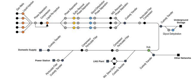
Figure 2 shows a simplified diagram of the journey gas takes from the well to the points of use. At the well, crude oil, condensate, water and sand tend to be present. Also, other liquids are added, with hydrate mitigators, corrosion inhibitors and bactericides particularly common. These treatments perform essential functions, but they also add to the gas stream’s liquid loading as it enters the front-end phase separation at the gas treatment plant. To maximize the plant’s efficiency, these liquids need to be removed before the gas enters the plant.
A detailed survey by Amine Experts demonstrates how vital effective front-end phase separation is. Based on 400 amine plant failure cases, the survey identified three main causes:
- Corrosion resulting from poor amine quality or insufficient regeneration;
- Foaming attributable to contaminated gas at the inlet; and
- Poor product quality from insufficient heat.
Each of the 400 cases cost the operators between $250,000 and $250 million. Two out of the three plant failure causes (poor amine quality and contaminated gas at the inlet) highlight the need for better filtration and phase separation as gas enters processing plants.
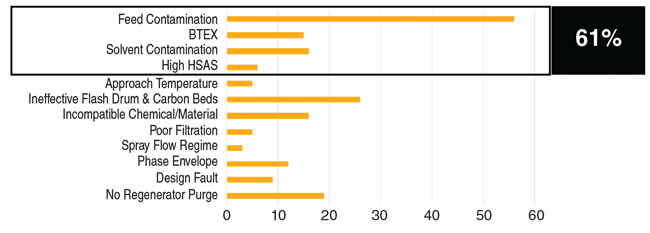
Figure 3 shows the causes of foaming in the survey’s failure cases. Four drivers of foaming result from inlet gas contamination, indicating that incorrect phase separation is the primary source (61%) of foaming events. By using process cameras to deepen their understanding of gas contamination at this stage of the process, engineers can take immediate action to avoid a foaming event, such as adding defoamer early. This response is a far more attractive solution than the common practice of cutting gas flow, and therefore output, to get foaming under control.
Over time, the plant can minimize foaming’s occurrence by conducting studies to understand when and how breakthrough occurs, implementing better maintenance practices and investing in more effective phase separation equipment. The camera’s data can help engineers justify these investments and verify that they work.
Today, foaming is such a major risk that many gas plants limit the gas flow rate below the optimum to create a margin in case of foaming. Process cameras give operators the confidence to run a little closer to the optimum in the knowledge they can react quickly if a liquid event occurs.
Boosting NGL Recoveries
As the gas moves through desulfurization and dehumidification, large quantities of liquid come into intimate contact with the gas. If these liquids go unseparated, liquid carryover will contaminate the next stage of the process, NGL removal. Once the gas is sweet and dry, the usual method of extracting NGLs to the greatest extent possible is to reduce the temperature of the gas, force the gas below its hydrocarbon dewpoint and separate the liquids.
When temperature reduction is achieved totally or partially by pressure reduction, it creates the perfect environment for a flowing gas to produce a sub-micron mist flow, the most difficult type of liquid to filter out. Effective technologies exist to separate mist flows, but they are so rarely implemented that such mist flows often remain in the gas stream after separation. As the gas warms back up, the liquids vaporize, saturating the vapor phase with hydrocarbons.
Because the pressure hydrocarbon dewpoint and temperature are the same, these hydrocarbons can be difficult to detect with dewpoint monitoring. This situation is exacerbated as sample systems intentionally separate anything that has already changed phase.
In these cases, operators do not gain the full financial benefit of NGL recovery but still have the expense associated with cooling large volumes of gas.
Promoting Accuracy
When liquids unexpectedly appear in dry gas systems, they can compromise flow measurements. Under federal law, the flow assurance and uncertainty budgets for fiscal flow measurements must detail and account for potential errors. Without a way to monitor liquid carryover, flow uncertainty budgets need to include a substantial margin to reflect liquids’ potential effects.
Liquid events can compromise flow measurements in two ways. First, when liquids are present, dry gas flowmeters will read in error, with these errors as high as 2% of the reading. By verifying that the gas is a single phase, process cameras can reduce this uncertainty.
These cameras have highlighted another way that liquids can add uncertainty to measurements: When liquid stratified flows occur, they often transport solids that litter the pipe floor. These solids initially travel in a slurry, but with the rapid gas moving above, the slurry slowly dries to solid matter and permanently reduces pipeline diameter.
If these restrictions occur in flow metering stations, even amounts as small as two or three millimeters can produce errors of 0.3%. With the overall uncertainty target for fiscal flow measurements being less than 0.5%, this creates a significant and permanent offset. It’s worth noting that the error is independent of the flowmeter type and calibration. Flow stations are usually unpiggable sections of the pipeline system that should be inspected and cleaned regularly.
Protecting Compressors
Gas that is contaminated with liquids also contributes to compressor maintenance costs. To see how significant this effect can be, consider a survey in which the United Kingdom’s Health and Safety Executive examined 71 compressor failures. Each failure cost $60,000-$120,000, plus loss of production.
The survey found that the main cause of failures was the interaction between wet gas and dry gas seals. When asked about the design life requirements for these seals, both compressor manufacturers and end users indicated they should last five years. However, actual life averaged only a year and 20 days.
Dry gas seals usually are labyrinth seals where the gap between static and rotating components is around five microns. In every failure, contaminated gas allowed liquids to get between the faces of the seal. The gap should be controlled by gas pressure, but when liquids or solids are present, they create a bridge across it that conducts heat and allows the two parts to touch. This contact accelerates wear, shortening the life of the seal significantly and, in some cases, causing a loss of containment.
We may never be able to eliminate the risk of liquids contamination, but we can do far better. By installing process cameras on pipelines and using machine learning to turn the feed into digestible metrics, engineers can quickly identify when mist or stratified flows make it past separators, then take steps to remediate the situation. This practice will:
- Reduce gas processing plants’ downtime;
- Enable greater NGL recoveries;
- Improve fiscal measurements’ accuracy; and
- Shrink compressor service costs.
These benefits frequently justify process cameras’ costs even before considering how much they improve safety. r
Editor’s Note: This article is based on “See What’s Happening in Your Pipeline: The Future of Gas Plant Management,” a white paper presented at the GPA Midstream Technical Conference, which was held April 3-6 in Plano Tx. The paper includes more examples of camera data and discusses liquid carryover’s implications for transmission pipeline operators.

PAUL STOCKWELL is the founder and managing director of Process Vision Ltd., which provides cameras that act as permanent monitors for gas/liquid separator efficiency. He has 35 years of experience working in oil and gas systems and a long history of focusing on moisture measurement. In addition to founding International Moisture Analysers in 1991, he served on working parties for the United Kingdom’s National Physical Laboratory to improve liquids measurement in dry gas. Stockwell also helped develop the first tunable diode laser system, which has become the industry-standard method for measuring moisture in natural gas. He is named inventor on 16 granted patents and has 22 pending patents.
For other great articles about exploration, drilling, completions and production, subscribe to The American Oil & Gas Reporter and bookmark www.aogr.com.


